-
Cancel

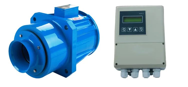
Submersible electro- magnetic flow meter consists of diving electromagnetic flow sensor and electromagnetic flow converter. Used in the continuous measurement of agricultural irrigation in open channel and close conduit or conducting liquid volume flow in the pipeline. Flow meter will be widely used in drainage of cities and towns, sewage treatment, water conservancy project, irrigation and other departments of the flow measurement.
Features:
Submersible electromagnetic flow meter is not only have measuring accurate of common electromagnetic flow meter, stable and reliable in work, but also have the below feature:
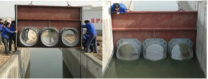
1. Apply to measurement of the open channel, the close conduit, the river.
2. Apply to measurement of the round, the rectangular, the trapezoidal, and the channels of others shape.
3. Using the simulation sensor( shunting model)can expand the flow measurement range.
IP68 underwater
Apply to measurement of the open channel, the close conduit, the river
Apply to measurement of the round, the rectangular, the trapezoidal, and the channels of others shape.
Item | Parameter |
Nominal diameter | DN100,DN200,DN400,DN600,DN800 |
Accuracy | ±0.5%,±2.5%( when it use together with the simulation sensor use) |
Flow range (flow velocity) | (0.5~1) ~(0.5~10)m/s |
Conductivity measured medium | >20uS/cm |
Maximum diving depth | 10m |
Electrode material | stainless steel 1Cr18Ni9Ti |
Medium temperature | 0~40℃ |
Output | 4~20mA |
Communication | RS232 or RS485 |
Power supply | 24VDCor 220VAC |
Display | LCD big screen back light display can show instantaneous flow rate, flow velocity, pressure, the total numbers of positive and negative cumulative battery level, clock and alarm prompt etc. |
Cable | 15m(standard) |
Protection | IP68 |
Installation location selection
1.Choose the even (dark) channel cross-section uniform, stable flow of water for the sensor installation position.
The sensor is mounted on the ram and ensures that the sensor is fully submerged under the liquid surface. The ram must have sufficient strength to support the sensor and be subjected to liquid power.
2.The straight length of the channel should be at least 5 times the channel width
3.The flow direction on the sensor and the measured medium flow direction in the channel must be the same.
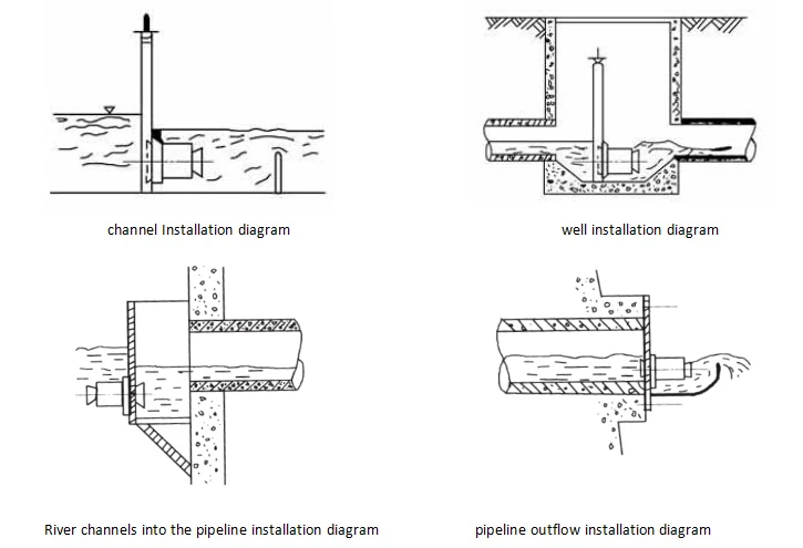
Sensor diameter selection
Max flow (m³/h)
Allowable head difference (m) | 50 | 100 | 200 | 300 | 500 | 800 | 1000 | 2000 | 5000 | 10000 |
0.5 | 100×1 | 100×2 | 100×3 200×1 | 100×4 200×1 | 200×2 | 200×3 400×1 | 200×3 400×1 | 200×6 400×2 | 400×4 800×1 600×2 | 600×3 800×2 |
0.4 | 100×1 | 100×2 | 100×3 200×1 | 100×4 200×1 | 200×2 | 200×3 400×1 | 200×3 400×1 | 200×6 400×2 | 400×4 800×1 600×2 | 600×4 800×2 |
0.3 | 100×1 | 100×2 | 100×3 200×1 | 200×2 | 200×2 | 200×3 400×1 | 200×4 400×1 | 400×2 | 400×5 800×1 600×2 | 600×4 800×3 |
0.2 | 100×1 | 100×2 | 100×4 200×1 | 200×2 | 200×3 400×1 | 200×4 400×1 | 200×5 400×2 | 400×3 600×1 | 400×5 800×2 600×3 | 600×5 800×3 |
0.1 | 100×1 | 100×2 200×1 | 200×2 | 200×2 | 200×3 400×1 | 200×5 400×2 | 200×6 400×2 | 400×3 | 600×4 800×3 | 600×7 800×4 |
Note:The value in the table is (sensor diameter mm) × (the total number of sensors and shunt models)
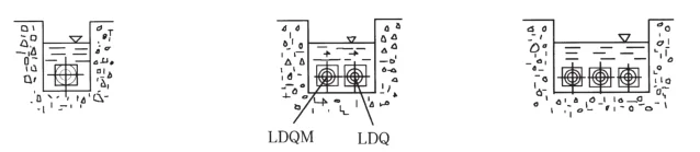
Electromagnetic flow sensor and simulation sensor together
Confirm the following parameters before order:
1.channel shape:Rectangular, trapezoidal, or other shape channels?
2.Channel width and height?
3.channel maximum flow?
GMF500- | Note | |||||
Diameter | DN*** | DN100,DN200,DN400,DN600,DN800(mm) | ||||
Power supply | 1 | 220VAC | ||||
2 | 24VDC | |||||
Output | 1 | 4-20mA | ||||
Communication | 1 | RS485 | ||||
2 | RS232 | |||||
Cable | 15 | Standard cable length | ||||
** | Customized(over 15m charge) | |||||